The conversion programming from RS Logix 500 to RS Logix 5000 seen versatility alone could make the conversion from the RS Logix 500 platform to the RS Logix 5000 platform a worthwhile venture. With four different programming languages at your disposal, almost every electro-mechanical control application conceivable can be accomplished through the implementation of Rockwell Software’s RS Logix 5000 software.
Due to the multiple programming languages, it was able to be shortened. Each programming language has a topic that it has been designed for. With this in mind, the Ladder logic pertaining to the heating zones was more suitable for function block diagrams than Ladder logic. The commands are more suitable to particular applications, therefore, shortened the code.
Another benefit is having the ability to program all inputs and outputs using descriptive tags. It was obvious through the project code writing processes that a program with tags would make a program not only easier to follow, but easier to troubleshoot too. Additionally, the ability to monitor and change tag values, while the program is online, has been a benefit. For example, gain values for a PIDE function block can be changed online to optimize your PIDE curve. The result of this tuning can be seen almost instantaneously and will not disrupt the other program functions.
Monday, June 21, 2010
Topic Definition Command of TELEMEC DDE Server
When the TELEMEC DDE server starts up, it first attempts to locate its configuration file by checking the WIN.INI file for path that was previously specified. If the path is not present in the WIN.INI file, the server will assume that the current working directory is to be used.
To start the server from an application directory configuration file other than the default configuration file a special switch is used. For example, invoke the File/Run command in File Manager or Program manager and enter the following:
TELEMEC /d:c:\directoryname
The user provides a connected micro PLC with an arbitrary name that is used as the DDE topic for all references to this PLC.
The following steps are taken to define the Topic attached to the PLC:
1. Invoke the Topic Definition…command. The Topic Definition dialog will appear:

2. To modify existing topic, select the topic name and click on Modify. To define a new topic, click on New. To remove an existing topic, click on Delete. The “TELEMEC Topic Definition” dialog will appear:

3. Enter the Topic Name, which corresponds, to the DDE Topic Name (The DDE Topic Name is entered in the ”DDE Access Name Definition” dialog box described in the Using the TELEMEC Server with InTouch section).
4. Click on the Com Port button to associate a topic with the communication port. Note: Additional topic may be associated with the same communication port later.
5. Set the Update Interval field to indicate the frequency the items/points on this topic will be read (polled). Default value is 1000 milliseconds.
When all entries have been made, click on OK to process the configuration for this topic.
Wednesday, June 16, 2010
Set Up EthernetIP for ControlLogix 5000
EDS file is an Ethernet IP EDS file specific to PumpSmart PS200 is available on the PS200 v5 Fieldbus Communications web page. Note that EDS files are only required when using RSNetworx for Ethernet in your application. This example is not using RSNetworx for Ethernet but is opening a generic Ethernet module in the ControlLogix 5000 PLC.
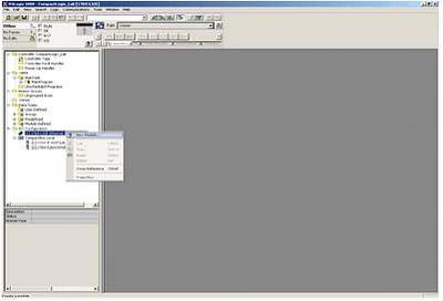
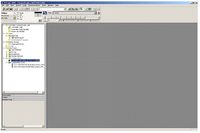
1. Open RS Logix 5000 and open an RSLogix 5000 program. Right click on the 1769-L32E Ethernet Port Local ENB.

2. Click on new Module.
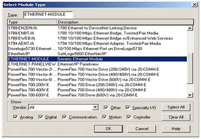
3. Select module Ethernet – Module
4. Program the following information below. The example below is using Input and Output Assembly instances 102 and 103. Once completed click finish.
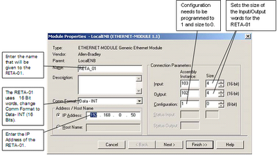
Input and Output sizes must match that used in the PS200. If writing to the Control Word and first reference, and reading the status word, motor speed, power, and smart flow, the output size must be 2 and the input size must be 4.
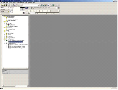
5. The RETA-01 is now added to the PLC I/O.
The problem or error that usually happened is unable to establish communications between the drive and the DCS (PLC). To avoid this problem:
• Be sure the module is located in slot 1 of the PS200.
• Check the MAC Addressing between the DCS and the drive specifically the IP and Subnet Mask.
• Be sure the Comm Rate and DHCP values are correct for the network.
• Be sure that parameter 31.01 state RETA-01.
• Be sure that you have refreshed the fieldbus module anytime after you change parameters in group 31.27.
1. Open RS Logix 5000 and open an RSLogix 5000 program. Right click on the 1769-L32E Ethernet Port Local ENB.
2. Click on new Module.

3. Select module Ethernet – Module

4. Program the following information below. The example below is using Input and Output Assembly instances 102 and 103. Once completed click finish.

Input and Output sizes must match that used in the PS200. If writing to the Control Word and first reference, and reading the status word, motor speed, power, and smart flow, the output size must be 2 and the input size must be 4.
5. The RETA-01 is now added to the PLC I/O.

The problem or error that usually happened is unable to establish communications between the drive and the DCS (PLC). To avoid this problem:
• Be sure the module is located in slot 1 of the PS200.
• Check the MAC Addressing between the DCS and the drive specifically the IP and Subnet Mask.
• Be sure the Comm Rate and DHCP values are correct for the network.
• Be sure that parameter 31.01 state RETA-01.
• Be sure that you have refreshed the fieldbus module anytime after you change parameters in group 31.27.
Omron SYSWIN for Creating Programs of PLC
The Omron SYSWIN software is designed for use with SYSMAC C and CV series Programmable Logic Controllers (PLCs). It provides straightforward method of creating and maintaining programs and testing their operation, either offline or connected to a PLC.
SYSWIN offers a comprehensive range of facilities for the PLC programmer, from program editing to full symbolic and network debugging, including:
• New program creation.
• Program storage and editing.
• Uploading and downloading code to a PLC.
• Program status during execution by PLC.
• Commenting programs: Symbolic addresses; Symbolic blocks and network frames; Comments.
• Maintenance of library files.
• Printing program and documentation.
• Conversion from other packages.
SYSWIN runs in the Microsoft Windows environment (version 3.1 and greater) on standard IBM and compatible 486 and Pentium based desktop computers. SYSWIN is intuitive to use, and allows the programmer to rapidly configure a specific project and enter network and program data. PLC programs can be constructed in either ladder or function plan format, and previously tested networks can be recalled from libraries. A special statement list editor allows PLC programs to be viewed and checked in their mnemonic format.
These features are designed to enable users to easily adapt PLC programs to changing requirements. Additional features allow the testing of new networks in supportive and safe environment.
Basic Physical Configuration of Modicon 984 PLCs
Modicon 984 PLCs are designed as a compatible family, the individual products in the family offer a wide range of functionality and physical attributes. This means you can use the right PLC for the right job – no matter what application.
The PLC is available in three basics physical configurations: compact, chassis mount and slot mount. Slot mount PLCs use an advance microprocessor architecture that incorporates system and power components into single compact modules. These modules mount in the primary 800 Series I/O sub racks. They include the 984-38x series. 984-48x series, 984-685 series, and 984-785 series PLCs. These models cover small to large control applications with logic solve time ranging from 1.0…5 milliseconds/K of user logic. Slot mount PLCs are the perfect choice for small to large applications such as machine or process control.
Chassis mount PLCs are housed in rugged four or seven slot chassis. These PLCs comprise a set of modular system boards that are individually installed in slots in the chassis. Chassis mount PLCs include the 984A, 984B, and 984X models. These models cover mid range to extra large control application with high performance logic solve time of about 0.75 milliseconds/K of user logic.
General 984 Environmental specifications as following:
• Ambient Temperature : 0 – 60oC , 32 – 140oF
• Humidity : 0 – 95% non condensing
• Shock : 10 G’s for 11 msec
• Vibration : .625 @50 – 500 Hz
• RFI/EMI Emission : Complies with applicable FCC requirements
• RFI/EMI Susceptibility : ML-STD-461B; CS02-Conducted; RS03-Radiated
• UL Listing :E54088
• CSA Listing : LR32678
TBCD instructions on Keyence PLC
BCD instructions on Keyence PLC : Transfer BCD (Binary-Coded Decimal).
Converts the content of [Acc (internal register)] to BCD (Binary-Coded Decimal).

illustration of TBCD instructions :
Binary Convert to BCD

Converts the content of [Acc (internal register)] to BCD (Binary-Coded Decimal).

illustration of TBCD instructions :
Binary Convert to BCD

Subscribe to:
Posts (Atom)

