Thursday, August 12, 2010
Automatic Gates using PLC
Information on Drawing Numbers for Automatic Gates using PLC :
1. Area Sensor (If there are objects, the sensor output OFF)
2. Area Sensor (If there are objects, the sensor output OFF)
3. Area Sensor (If there are objects, the sensor output OFF)
4. Area Sensor (If there are objects, the sensor output OFF)
5. Electric Motor And Gearbox
6. Limit Switch for Open gate condition
7. Limit Switch for Closed gate conditions
8. Gate
Number Of Inputs and Output PLC applied :
1. Number Of Inputs PLC is 6 Input :
--- 4 Unit Input for Area Sensor 1,2,3,and 4.
--- 1 Unit Input for Limit Switch for Open gate.
--- 1 Unit Input for Limit Switch for Closed gate.
--- Total Number Of Inputs PLC is Minimum 6 Input Unit.
2. Number Of Output PLC is 2 Output :
--- 1 Unit Output to contactor for Electric Motor (Open Gate ).
--- 1 Unit Output to contactor for Electric Motor (Close Gate ).
--- Total Number Of Outputs PLC is Minimum 2 Output Unit.
Sequence PLC Programming for Automatic Gates :
1. Open Gate
a. If Area Sensor 1 = OFF Then Electric Motor for Open Gate = ON.
b. If Limit Switch for Open gate = ON Then Electric Motor for Open Gate = OFF.
c. Electric Motor for Close Gate = always OFF
2. Close Gate
a. If Area Sensor 4 = OFF AND Area Sensor 2 = ON AND Area Sensor 3 = ON Then Electric Motor for Close Gate = ON.
b. If Electric Motor for Close Gate = ON AND Area Sensor 2 = OFF OR Area Sensor 3 = OFF Then Electric Motor for Close Gate = OFF AND Electric Motor for Open Gate = ON.
Note : For All Area Sensor : If there are objects, the sensor output OFF
GE Substation Automation Components
Software application
A powerful suite of flexible, user friendly software applications and graphical user-interface modules are available. These advance user interface and easy to configure tools enable improved date reporting and data base configuration management.
Network communications
A range of network components are available to tie and new legacy equipment into one unified system. GE can provide secure and reliable communications media based on experience and expertise in numerous network systems.
Intelligent Electronic Devices
A family of modular and flexible intelligent electronic devices is available for solving the biggest challenge of integrating relays from existing substations and new systems. Our relay family provides the latest for relay integration, protection, and control, with high speed, open standard peer-to-peer communication for connecting directly to the LAN.
Gateways/Servers
Robust system for monitoring a controlling substation device as well as for performance automation, IED gateways, and host communication functions. The systems have the processing power to monitor and control over 40 IEDs and thousands of I/O points.
Monitors and sensors
With a portfolio of sophisticated monitoring and diagnostics systems for critical substation equipment, remote monitoring of performance and critical fault detection is achievable. These advance systems enable you to improve performance and service reliability as well as extend the useful life of critical assets.
Feeder automation
Distribution Automation Remote Terminals equipped with auto-section-alizing and automation restoration software can dramatically reduce a customer’s outage frequency.
Monday, June 21, 2010
The Benefits of Conversion RS Logix 500 to RS Logix 5000
The conversion programming from RS Logix 500 to RS Logix 5000 seen versatility alone could make the conversion from the RS Logix 500 platform to the RS Logix 5000 platform a worthwhile venture. With four different programming languages at your disposal, almost every electro-mechanical control application conceivable can be accomplished through the implementation of Rockwell Software’s RS Logix 5000 software.
Due to the multiple programming languages, it was able to be shortened. Each programming language has a topic that it has been designed for. With this in mind, the Ladder logic pertaining to the heating zones was more suitable for function block diagrams than Ladder logic. The commands are more suitable to particular applications, therefore, shortened the code.
Another benefit is having the ability to program all inputs and outputs using descriptive tags. It was obvious through the project code writing processes that a program with tags would make a program not only easier to follow, but easier to troubleshoot too. Additionally, the ability to monitor and change tag values, while the program is online, has been a benefit. For example, gain values for a PIDE function block can be changed online to optimize your PIDE curve. The result of this tuning can be seen almost instantaneously and will not disrupt the other program functions.
Topic Definition Command of TELEMEC DDE Server
When the TELEMEC DDE server starts up, it first attempts to locate its configuration file by checking the WIN.INI file for path that was previously specified. If the path is not present in the WIN.INI file, the server will assume that the current working directory is to be used.
To start the server from an application directory configuration file other than the default configuration file a special switch is used. For example, invoke the File/Run command in File Manager or Program manager and enter the following:
TELEMEC /d:c:\directoryname
The user provides a connected micro PLC with an arbitrary name that is used as the DDE topic for all references to this PLC.
The following steps are taken to define the Topic attached to the PLC:
1. Invoke the Topic Definition…command. The Topic Definition dialog will appear:

2. To modify existing topic, select the topic name and click on Modify. To define a new topic, click on New. To remove an existing topic, click on Delete. The “TELEMEC Topic Definition” dialog will appear:

3. Enter the Topic Name, which corresponds, to the DDE Topic Name (The DDE Topic Name is entered in the ”DDE Access Name Definition” dialog box described in the Using the TELEMEC Server with InTouch section).
4. Click on the Com Port button to associate a topic with the communication port. Note: Additional topic may be associated with the same communication port later.
5. Set the Update Interval field to indicate the frequency the items/points on this topic will be read (polled). Default value is 1000 milliseconds.
When all entries have been made, click on OK to process the configuration for this topic.
Wednesday, June 16, 2010
Set Up EthernetIP for ControlLogix 5000
EDS file is an Ethernet IP EDS file specific to PumpSmart PS200 is available on the PS200 v5 Fieldbus Communications web page. Note that EDS files are only required when using RSNetworx for Ethernet in your application. This example is not using RSNetworx for Ethernet but is opening a generic Ethernet module in the ControlLogix 5000 PLC.
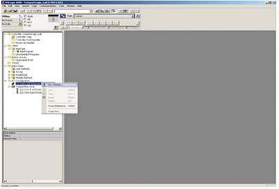
1. Open RS Logix 5000 and open an RSLogix 5000 program. Right click on the 1769-L32E Ethernet Port Local ENB.

2. Click on new Module.
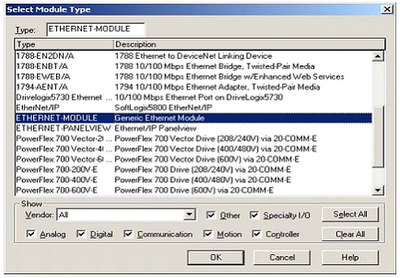
3. Select module Ethernet – Module
4. Program the following information below. The example below is using Input and Output Assembly instances 102 and 103. Once completed click finish.
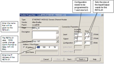
Input and Output sizes must match that used in the PS200. If writing to the Control Word and first reference, and reading the status word, motor speed, power, and smart flow, the output size must be 2 and the input size must be 4.
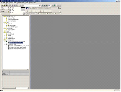
5. The RETA-01 is now added to the PLC I/O.
The problem or error that usually happened is unable to establish communications between the drive and the DCS (PLC). To avoid this problem:
• Be sure the module is located in slot 1 of the PS200.
• Check the MAC Addressing between the DCS and the drive specifically the IP and Subnet Mask.
• Be sure the Comm Rate and DHCP values are correct for the network.
• Be sure that parameter 31.01 state RETA-01.
• Be sure that you have refreshed the fieldbus module anytime after you change parameters in group 31.27.
1. Open RS Logix 5000 and open an RSLogix 5000 program. Right click on the 1769-L32E Ethernet Port Local ENB.
2. Click on new Module.

3. Select module Ethernet – Module

4. Program the following information below. The example below is using Input and Output Assembly instances 102 and 103. Once completed click finish.

Input and Output sizes must match that used in the PS200. If writing to the Control Word and first reference, and reading the status word, motor speed, power, and smart flow, the output size must be 2 and the input size must be 4.
5. The RETA-01 is now added to the PLC I/O.

The problem or error that usually happened is unable to establish communications between the drive and the DCS (PLC). To avoid this problem:
• Be sure the module is located in slot 1 of the PS200.
• Check the MAC Addressing between the DCS and the drive specifically the IP and Subnet Mask.
• Be sure the Comm Rate and DHCP values are correct for the network.
• Be sure that parameter 31.01 state RETA-01.
• Be sure that you have refreshed the fieldbus module anytime after you change parameters in group 31.27.
Omron SYSWIN for Creating Programs of PLC
The Omron SYSWIN software is designed for use with SYSMAC C and CV series Programmable Logic Controllers (PLCs). It provides straightforward method of creating and maintaining programs and testing their operation, either offline or connected to a PLC.
SYSWIN offers a comprehensive range of facilities for the PLC programmer, from program editing to full symbolic and network debugging, including:
• New program creation.
• Program storage and editing.
• Uploading and downloading code to a PLC.
• Program status during execution by PLC.
• Commenting programs: Symbolic addresses; Symbolic blocks and network frames; Comments.
• Maintenance of library files.
• Printing program and documentation.
• Conversion from other packages.
SYSWIN runs in the Microsoft Windows environment (version 3.1 and greater) on standard IBM and compatible 486 and Pentium based desktop computers. SYSWIN is intuitive to use, and allows the programmer to rapidly configure a specific project and enter network and program data. PLC programs can be constructed in either ladder or function plan format, and previously tested networks can be recalled from libraries. A special statement list editor allows PLC programs to be viewed and checked in their mnemonic format.
These features are designed to enable users to easily adapt PLC programs to changing requirements. Additional features allow the testing of new networks in supportive and safe environment.
Basic Physical Configuration of Modicon 984 PLCs
Modicon 984 PLCs are designed as a compatible family, the individual products in the family offer a wide range of functionality and physical attributes. This means you can use the right PLC for the right job – no matter what application.
The PLC is available in three basics physical configurations: compact, chassis mount and slot mount. Slot mount PLCs use an advance microprocessor architecture that incorporates system and power components into single compact modules. These modules mount in the primary 800 Series I/O sub racks. They include the 984-38x series. 984-48x series, 984-685 series, and 984-785 series PLCs. These models cover small to large control applications with logic solve time ranging from 1.0…5 milliseconds/K of user logic. Slot mount PLCs are the perfect choice for small to large applications such as machine or process control.
Chassis mount PLCs are housed in rugged four or seven slot chassis. These PLCs comprise a set of modular system boards that are individually installed in slots in the chassis. Chassis mount PLCs include the 984A, 984B, and 984X models. These models cover mid range to extra large control application with high performance logic solve time of about 0.75 milliseconds/K of user logic.
General 984 Environmental specifications as following:
• Ambient Temperature : 0 – 60oC , 32 – 140oF
• Humidity : 0 – 95% non condensing
• Shock : 10 G’s for 11 msec
• Vibration : .625 @50 – 500 Hz
• RFI/EMI Emission : Complies with applicable FCC requirements
• RFI/EMI Susceptibility : ML-STD-461B; CS02-Conducted; RS03-Radiated
• UL Listing :E54088
• CSA Listing : LR32678
TBCD instructions on Keyence PLC
BCD instructions on Keyence PLC : Transfer BCD (Binary-Coded Decimal).
Converts the content of [Acc (internal register)] to BCD (Binary-Coded Decimal).

illustration of TBCD instructions :
Binary Convert to BCD

Converts the content of [Acc (internal register)] to BCD (Binary-Coded Decimal).

illustration of TBCD instructions :
Binary Convert to BCD

Saturday, May 29, 2010
Mini Programmable Logic Controllers
The project configuration using RSLOGIX 5000 programming software:
• Tags Database: Open the PLC project with RSLogix 5000 programming software. Right click on the controller tags folder and choose the Export Tags option from pop-up menu. Make sure to select RSLogix 5000 Import/Export File(*.CSV) option on the Save as Type combo box and the All tags in project in the scope box. Click the Export button to create the CSV file with tags database configuration.
• User-Define Tags: Open the PLC project with RSLogix 5000 programming software. Select File-->Save as from the main menu. Make sure to select RSLogix 5000 Import/Export File (*.L5K) option in the Save as type box. Click the Save button to create the L5K file with the User-Defined Tags configuration.
The ABCIP driver enables communication between IWS and the Allen Bradley ControlLogix PLC with the 1756-ENET interface for Ethernet communication. The ABCIP supports routing communication for two levels. You can exchange data with ControlLogix PLC directly connected in the rack where the 1756-ENET module is connected, or you can address other PLCs connected to the ControlLogix rack via:
• 1756-ENET: Communication interface for Ethernet/IP protocol.
• 1756-DHRIO: Communication interface for DH+ or remote I/O (RIO).
• 1756-CNB: Communication interface for ControlNet.
ControlLogix CPU directly connected where the 1756-ENET interface is connected as shown in picture below:

The following picture is the ABCIP driver to access remote PLC connected in Ethernet/IP, DH+, RIO or ControlNet networks, via the 1756-ENET interface module:

The Advantages of Allen-Bradley RSLogix 5000 in Manufacturing
In the vast world of automated manufacturing programmable logic controller (PLC) are one of the most reliable and effective means of controlling any electro-mechanical process. One of the manufacturing that using PLC is a high strength pultruded fiberglass reinforced polymer composites. Previously this manufacturing was using RSLogix500, but now there is the latest of Rockwell PLC software that is RSLogix5000.
RSLogix5000 is the latest in the Allen-Bradley series of PLC software. RSLogix5000 uses one software package consisting of four styles of programming languages: Ladder logic, structured text, function block diagrams, and sequential function charts. These programming languages can be used for control process, drives, sequential, and motion control. This system allows the user create command labels through a tag-based platform.
The parameters for that command can be specified to be a bit, integer, etc. Rockwell Software has stated the following about the RSLogix5000 platform:
• Intuitive and simple to use.
• Compliant IEC1131-3 interface.
• Structured programming by way of symbols and arrays.
• Instruction set supplying multiple applications.
• Integrates DCS systems or single-loop controllers and dedicated servo or drive systems into one environment.
• Online troubleshooting capabilities.
• Ability to create new tags while online.
There are still have others advantages of RSLogix5000.
IWS Interface for PLC Allen-Bradley ControlLogix 5000
This article will describe the interfaces provided by InduSoft Web Studio (IWS) to exchange data with ControlLogix PLCs from Allen-Bradley:
• IWS for RSLogix5000 CSV database : using this tool user can import the tag names and the communication setting from the PLC program. IWS create not only the tags in the application tags database but also the communication driver worksheet automatically. This interface reduces dramatically the time invested to integrate the SCADA/HMI software with the ControlLogix PLC and reduces the configuration errors.
• ABCIP Communication Driver: this driver implements the CIP protocol over Ethernet/IP and exchanges data with the ControlLogix PLC during the runtime, using the tag names configured in the PLC project.
IWS enables you to create or add to Tags database by importing taj=gs froman external application database, including:
• OPC server databases.
• ODBC databases.
• CXV databases.
• PanelBuilder Import Wizard.
• RSLogix 5000 CSV databases (including Allen-Bradley RSLogix CSV files).
When you select File-->Import Wizard, an Import Wizard dialog displays to walk you through the process of importing tags:

To begin you must specify the type of database source you are going to use.
• Select RSLogix 5000 CSV from the source type list, and then click the Next button.
• When the next Wizard screen displays, click a radio button in the Option pane to specify of the following options:

This interface allows the user to import the Tags Database and the communication interface configuration form the ControlLogix/FlexLogix PLC program files.
Timer Countdown with PLC


Information on Drawing Numbers for Timer Countdown with PLC :
1. Timer Countdown with Two 7 Segment
2. PLC or Programmable Logic Controller
3. Toggle Switch ( ON - OFF )
4. Lamp to signal countdown completion
Two Seven Segment and PLC Output:-

Information for One Seven Segment to PLC :-
1. one 7 Segment
2. common anode seven segment
3. common cathode seven segment
Number Of Inputs and Output PLC applied :-
1. Number Of Inputs PLC is 1 Input :
--- 1 Unit Input for Toggle Switch ( ON - OFF ).
--- Total Number Of Inputs PLC is Minimum 1 Input Unit.
2. Number Of Output PLC is 15 Output :
--- 14 Unit Output for two Seven Segment.
--- 1 Unit Output for Lamp to signal countdown completion.
--- Total Number Of Outputs PLC is Minimum 15 Output Unit.
Sequence PLC Programming for Timer Countdown :-
1. Timer Countdown Display starts from 30 seconds
-> If Toggle Switch = OFF Then Timer Countdown display = 30.
2. Count down from 30 seconds to 00 seconds
-> If Toggle Switch = ON Then Timer Countdown display = count down from 30 seconds to 00 seconds.
3. After 00 seconds then Lamp: ON
-> If Timer Countdown display = 00 Then Lamp = ON.
4. Reset for Timer Countdown
-> If Toggle Switch = OFF Then Timer Countdown display = 30 And Lamp = OFF.
Wednesday, May 26, 2010
Solid-state relays
As versatile as electromechanical relays can be, they do suffer many limitations. They can be expensive to build, have a limited contact cycle life, take up a lot of room, and switch slowly, compared to modern semiconductor devices. These limitations are especially true for large power contactor relays. To address these limitations, many relay manufacturers offer "solid-state" relays, which use an SCR, TRIAC, or transistor output instead of mechanical contacts to switch the controlled power. The output device (SCR, TRIAC, or transistor) is optically-coupled to an LED light source inside the relay. The relay is turned on by energizing this LED, usually with low-voltage DC power. This optical isolation between input to output rivals the best that electromechanical relays can offer.

Being solid-state devices, there are no moving parts to wear out, and they are able to switch on and off much faster than any mechanical relay armature can move. There is no sparking between contacts, and no problems with contact corrosion. However, solid-state relays are still too expensive to build in very high current ratings, and so electromechanical contactors continue to dominate that application in industry today.
One significant advantage of a solid-state SCR or TRIAC relay over an electromechanical device is its natural tendency to open the AC circuit only at a point of zero load current. Because SCR's and TRIAC's are thyristors, their inherent hysteresis maintains circuit continuity after the LED is de-energized until the AC current falls below a threshold value (the holding current). In practical terms what this means is the circuit will never be interrupted in the middle of a sine wave peak. Such untimely interruptions in a circuit containing substantial inductance would normally produce large voltage spikes due to the sudden magnetic field collapse around the inductance. This will not happen in a circuit broken by an SCR or TRIAC. This feature is called zero-crossover switching.
One disadvantage of solid state relays is their tendency to fail "shorted" on their outputs, while electromechanical relay contacts tend to fail "open." In either case, it is possible for a relay to fail in the other mode, but these are the most common failures. Because a "fail-open" state is generally considered safer than a "fail-closed" state, electromechanical relays are still favored over their solid-state counterparts in many applications.
Fail-safe design
Logic circuits, whether comprised of electromechanical relays or solid-state gates, can be built in many different ways to perform the same functions. There is usually no one "correct" way to design a complex logic circuit, but there are usually ways that are better than others.
In control systems, safety is (or at least should be) an important design priority. If there are multiple ways in which a digital control circuit can be designed to perform a task, and one of those ways happens to hold certain advantages in safety over the others, then that design is the better one to choose.
Let's take a look at a simple system and consider how it might be implemented in relay logic. Suppose that a large laboratory or industrial building is to be equipped with a fire alarm system, activated by any one of several latching switches installed throughout the facility. The system should work so that the alarm siren will energize if any one of the switches is actuated. At first glance it seems as though the relay logic should be incredibly simple: just use normally-open switch contacts and connect them all in parallel with each other:

Essentially, this is the OR logic function implemented with four switch inputs. We could expand this circuit to include any number of switch inputs, each new switch being added to the parallel network, but I'll limit it to four in this example to keep things simple. At any rate, it is an elementary system and there seems to be little possibility of trouble.

If this failure were to occur, the result would be that Switch #2 would no longer energize the siren if actuated. This, obviously, is not good in a fire alarm system. Unless the system were regularly tested (a good idea anyway), no one would know there was a problem until someone tried to use that switch in an emergency.
What if the system were re-engineered so as to sound the alarm in the event of an open failure? That way, a failure in the wiring would result in a false alarm, a scenario much more preferable than that of having a switch silently fail and not function when needed. In order to achieve this design goal, we would have to re-wire the switches so that an open contact sounded the alarm, rather than a closed contact. That being the case, the switches will have to be normally-closed and in series with each other, powering a relay coil which then activates a normally-closed contact for the siren:
Except in the event of a wiring failure, that is. The nature of electric circuits is such that "open" failures (open switch contacts, broken wire connections, open relay coils, blown fuses, etc.) are statistically more likely to occur than any other type of failure. With that in mind, it makes sense to engineer a circuit to be as tolerant as possible to such a failure. Let's suppose that a wire connection for Switch #2 were to fail open:

When all switches are unactuated (the regular operating state of this system), relay CR1 will be energized, thus keeping contact CR1 open, preventing the siren from being powered. However, if any of the switches are actuated, relay CR1 will de-energize, closing contact CR1 and sounding the alarm. Also, if there is a break in the wiring anywhere in the top rung of the circuit, the alarm will sound. When it is discovered that the alarm is false, the workers in the facility will know that something failed in the alarm system and that it needs to be repaired.
Granted, the circuit is more complex than it was before the addition of the control relay, and the system could still fail in the "silent" mode with a broken connection in the bottom rung, but its still a safer design than the original circuit, and thus preferable from the standpoint of safety.
This design of circuit is referred to as fail-safe, due to its intended design to default to the safest mode in the event of a common failure such as a broken connection in the switch wiring. Fail-safe design always starts with an assumption as to the most likely kind of wiring or component failure, and then tries to configure things so that such a failure will cause the circuit to act in the safest way, the "safest way" being determined by the physical characteristics of the process.
Take for example an electrically-actuated (solenoid) valve for turning on cooling water to a machine. Energizing the solenoid coil will move an armature which then either opens or closes the valve mechanism, depending on what kind of valve we specify. A spring will return the valve to its "normal" position when the solenoid is de-energized. We already know that an open failure in the wiring or solenoid coil is more likely than a short or any other type of failure, so we should design this system to be in its safest mode with the solenoid de-energized.
If its cooling water we're controlling with this valve, chances are it is safer to have the cooling water turn on in the event of a failure than to shut off, the consequences of a machine running without coolant usually being severe. This means we should specify a valve that turns on (opens up) when de-energized and turns off (closes down) when energized. This may seem "backwards" to have the valve set up this way, but it will make for a safer system in the end.
One interesting application of fail-safe design is in the power generation and distribution industry, where large circuit breakers need to be opened and closed by electrical control signals from protective relays. If a 50/51 relay (instantaneous and time overcurrent) is going to command a circuit breaker to trip (open) in the event of excessive current, should we design it so that the relay closes a switch contact to send a "trip" signal to the breaker, or opens a switch contact to interrupt a regularly "on" signal to initiate a breaker trip? We know that an open connection will be the most likely to occur, but what is the safest state of the system: breaker open or breaker closed?
At first, it would seem that it would be safer to have a large circuit breaker trip (open up and shut off power) in the event of an open fault in the protective relay control circuit, just like we had the fire alarm system default to an alarm state with any switch or wiring failure. However, things are not so simple in the world of high power. To have a large circuit breaker indiscriminately trip open is no small matter, especially when customers are depending on the continued supply of electric power to supply hospitals, telecommunications systems, water treatment systems, and other important infrastructures. For this reason, power system engineers have generally agreed to design protective relay circuits to output a closed contact signal (power applied) to open large circuit breakers, meaning that any open failure in the control wiring will go unnoticed, simply leaving the breaker in the status quo position.
Is this an ideal situation? Of course not. If a protective relay detects an overcurrent condition while the control wiring is failed open, it will not be able to trip open the circuit breaker. Like the first fire alarm system design, the "silent" failure will be evident only when the system is needed. However, to engineer the control circuitry the other way -- so that any open failure would immediately shut the circuit breaker off, potentially blacking out large potions of the power grid -- really isn't a better alternative.
An entire book could be written on the principles and practices of good fail-safe system design. At least here, you know a couple of the fundamentals: that wiring tends to fail open more often than shorted, and that an electrical control system's (open) failure mode should be such that it indicates and/or actuates the real-life process in the safest alternative mode. These fundamental principles extend to non-electrical systems as well: identify the most common mode of failure, then engineer the system so that the probable failure mode places the system in the safest condition.
* REVIEW:
* The goal of fail-safe design is to make a control system as tolerant as possible to likely wiring or component failures.
* The most common type of wiring and component failure is an "open" circuit, or broken connection. Therefore, a fail-safe system should be designed to default to its safest mode of operation in the case of an open circuit.
Motor control circuits
The interlock contacts installed in the previous section's motor control circuit work fine, but the motor will run only as long as each pushbutton switch is held down. If we wanted to keep the motor running even after the operator takes his or her hand off the control switch(es), we could change the circuit in a couple of different ways: we could replace the pushbutton switches with toggle switches, or we could add some more relay logic to "latch" the control circuit with a single, momentary actuation of either switch. Let's see how the second approach is implemented, since it is commonly used in industry:

When the "Forward" pushbutton is actuated, M1 will energize, closing the normally-open auxiliary contact in parallel with that switch. When the pushbutton is released, the closed M1 auxiliary contact will maintain current to the coil of M1, thus latching the "Forward" circuit in the "on" state. The same sort of thing will happen when the "Reverse" pushbutton is pressed. These parallel auxiliary contacts are sometimes referred to as seal-in contacts, the word "seal" meaning essentially the same thing as the word latch.
However, this creates a new problem: how to stop the motor! As the circuit exists right now, the motor will run either forward or backward once the corresponding pushbutton switch is pressed, and will continue to run as long as there is power. To stop either circuit (forward or backward), we require some means for the operator to interrupt power to the motor contactors. We'll call this new switch, Stop:

Now, if either forward or reverse circuits are latched, they may be "unlatched" by momentarily pressing the "Stop" pushbutton, which will open either forward or reverse circuit, de-energizing the energized contactor, and returning the seal-in contact to its normal (open) state. The "Stop" switch, having normally-closed contacts, will conduct power to either forward or reverse circuits when released.
So far, so good. Let's consider another practical aspect of our motor control scheme before we quit adding to it. If our hypothetical motor turned a mechanical load with a lot of momentum, such as a large air fan, the motor might continue to coast for a substantial amount of time after the stop button had been pressed. This could be problematic if an operator were to try to reverse the motor direction without waiting for the fan to stop turning. If the fan was still coasting forward and the "Reverse" pushbutton was pressed, the motor would struggle to overcome that inertia of the large fan as it tried to begin turning in reverse, drawing excessive current and potentially reducing the life of the motor, drive mechanisms, and fan. What we might like to have is some kind of a time-delay function in this motor control system to prevent such a premature startup from happening.
Let's begin by adding a couple of time-delay relay coils, one in parallel with each motor contactor coil. If we use contacts that delay returning to their normal state, these relays will provide us a "memory" of which direction the motor was last powered to turn. What we want each time-delay contact to do is to open the starting-switch leg of the opposite rotation circuit for several seconds, while the fan coasts to a halt.

If the motor has been running in the forward direction, both M1 and TD1 will have been energized. This being the case, the normally-closed, timed-closed contact of TD1 between wires 8 and 5 will have immediately opened the moment TD1 was energized. When the stop button is pressed, contact TD1 waits for the specified amount of time before returning to its normally-closed state, thus holding the reverse pushbutton circuit open for the duration so M2 can't be energized. When TD1 times out, the contact will close and the circuit will allow M2 to be energized, if the reverse pushbutton is pressed. In like manner, TD2 will prevent the "Forward" pushbutton from energizing M1 until the prescribed time delay after M2 (and TD2) have been de-energized.
The careful observer will notice that the time-interlocking functions of TD1 and TD2 render the M1 and M2 interlocking contacts redundant. We can get rid of auxiliary contacts M1 and M2 for interlocks and just use TD1 and TD2's contacts, since they immediately open when their respective relay coils are energized, thus "locking out" one contactor if the other is energized. Each time delay relay will serve a dual purpose: preventing the other contactor from energizing while the motor is running, and preventing the same contactor from energizing until a prescribed time after motor shutdown. The resulting circuit has the advantage of being simpler than the previous example:

* REVIEW:
* Motor contactor (or "starter") coils are typically designated by the letter "M" in ladder logic diagrams.
* Continuous motor operation with a momentary "start" switch is possible if a normally-open "seal-in" contact from the contactor is connected in parallel with the start switch, so that once the contactor is energized it maintains power to itself and keeps itself "latched" on.
* Time delay relays are commonly used in large motor control circuits to prevent the motor from being started (or reversed) until a certain amount of time has elapsed from an event.
Programmable logic controllers
Before the advent of solid-state logic circuits, logical control systems were designed and built exclusively around electromechanical relays. Relays are far from obsolete in modern design, but have been replaced in many of their former roles as logic-level control devices, relegated most often to those applications demanding high current and/or high voltage switching.
Systems and processes requiring "on/off" control abound in modern commerce and industry, but such control systems are rarely built from either electromechanical relays or discrete logic gates. Instead, digital computers fill the need, which may be programmed to do a variety of logical functions.
In the late 1960's an American company named Bedford Associates released a computing device they called the MODICON. As an acronym, it meant Modular Digital Controller, and later became the name of a company division devoted to the design, manufacture, and sale of these special-purpose control computers. Other engineering firms developed their own versions of this device, and it eventually came to be known in non-proprietary terms as a PLC, or Programmable Logic Controller. The purpose of a PLC was to directly replace electromechanical relays as logic elements, substituting instead a solid-state digital computer with a stored program, able to emulate the interconnection of many relays to perform certain logical tasks.
A PLC has many "input" terminals, through which it interprets "high" and "low" logical states from sensors and switches. It also has many output terminals, through which it outputs "high" and "low" signals to power lights, solenoids, contactors, small motors, and other devices lending themselves to on/off control. In an effort to make PLCs easy to program, their programming language was designed to resemble ladder logic diagrams. Thus, an industrial electrician or electrical engineer accustomed to reading ladder logic schematics would feel comfortable programming a PLC to perform the same control functions.
PLCs are industrial computers, and as such their input and output signals are typically 120 volts AC, just like the electromechanical control relays they were designed to replace. Although some PLCs have the ability to input and output low-level DC voltage signals of the magnitude used in logic gate circuits, this is the exception and not the rule.
Signal connection and programming standards vary somewhat between different models of PLC, but they are similar enough to allow a "generic" introduction to PLC programming here. The following illustration shows a simple PLC, as it might appear from a front view. Two screw terminals provide connection to 120 volts AC for powering the PLC's internal circuitry, labeled L1 and L2. Six screw terminals on the left-hand side provide connection to input devices, each terminal representing a different input "channel" with its own "X" label. The lower-left screw terminal is a "Common" connection, which is generally connected to L2 (neutral) of the 120 VAC power source.

Inside the PLC housing, connected between each input terminal and the Common terminal, is an opto-isolator device (Light-Emitting Diode) that provides an electrically isolated "high" logic signal to the computer's circuitry (a photo-transistor interprets the LED's light) when there is 120 VAC power applied between the respective input terminal and the Common terminal. An indicating LED on the front panel of the PLC gives visual indication of an "energized" input:

Output signals are generated by the PLC's computer circuitry activating a switching device (transistor, TRIAC, or even an electromechanical relay), connecting the "Source" terminal to any of the "Y-" labeled output terminals. The "Source" terminal, correspondingly, is usually connected to the L1 side of the 120 VAC power source. As with each input, an indicating LED on the front panel of the PLC gives visual indication of an "energized" output:

In this way, the PLC is able to interface with real-world devices such as switches and solenoids.
The actual logic of the control system is established inside the PLC by means of a computer program. This program dictates which output gets energized under which input conditions. Although the program itself appears to be a ladder logic diagram, with switch and relay symbols, there are no actual switch contacts or relay coils operating inside the PLC to create the logical relationships between input and output. These are imaginary contacts and coils, if you will. The program is entered and viewed via a personal computer connected to the PLC's programming port.
Consider the following circuit and PLC program:

When the pushbutton switch is unactuated (unpressed), no power is sent to the X1 input of the PLC. Following the program, which shows a normally-open X1 contact in series with a Y1 coil, no "power" will be sent to the Y1 coil. Thus, the PLC's Y1 output remains de-energized, and the indicator lamp connected to it remains dark.
If the pushbutton switch is pressed, however, power will be sent to the PLC's X1 input. Any and all X1 contacts appearing in the program will assume the actuated (non-normal) state, as though they were relay contacts actuated by the energizing of a relay coil named "X1". In this case, energizing the X1 input will cause the normally-open X1 contact will "close," sending "power" to the Y1 coil. When the Y1 coil of the program "energizes," the real Y1 output will become energized, lighting up the lamp connected to it:

It must be understood that the X1 contact, Y1 coil, connecting wires, and "power" appearing in the personal computer's display are all virtual. They do not exist as real electrical components. They exist as commands in a computer program -- a piece of software only -- that just happens to resemble a real relay schematic diagram.
Equally important to understand is that the personal computer used to display and edit the PLC's program is not necessary for the PLC's continued operation. Once a program has been loaded to the PLC from the personal computer, the personal computer may be unplugged from the PLC, and the PLC will continue to follow the programmed commands. I include the personal computer display in these illustrations for your sake only, in aiding to understand the relationship between real-life conditions (switch closure and lamp status) and the program's status ("power" through virtual contacts and virtual coils).
The true power and versatility of a PLC is revealed when we want to alter the behavior of a control system. Since the PLC is a programmable device, we can alter its behavior by changing the commands we give it, without having to reconfigure the electrical components connected to it. For example, suppose we wanted to make this switch-and-lamp circuit function in an inverted fashion: push the button to make the lamp turn off, and release it to make it turn on. The "hardware" solution would require that a normally-closed pushbutton switch be substituted for the normally-open switch currently in place. The "software" solution is much easier: just alter the program so that contact X1 is normally-closed rather than normally-open.
In the following illustration, we have the altered system shown in the state where the pushbutton is unactuated (not being pressed):
This section on programmable logic controllers illustrates just a small sample of their capabilities. As computers, PLCs can perform timing functions (for the equivalent of time-delay relays), drum sequencing, and other advanced functions with far greater accuracy and reliability than what is possible using electromechanical logic devices. Most PLCs have the capacity for far more than six inputs and six outputs. The following photograph shows several input and output modules of a single Allen-Bradley PLC.

With each module having sixteen "points" of either input or output, this PLC has the ability to monitor and control dozens of devices. Fit into a control cabinet, a PLC takes up little room, especially considering the equivalent space that would be needed by electromechanical relays to perform the same functions:

One advantage of PLCs that simply cannot be duplicated by electromechanical relays is remote monitoring and control via digital computer networks. Because a PLC is nothing more than a special-purpose digital computer, it has the ability to communicate with other computers rather easily. The following photograph shows a personal computer displaying a graphic image of a real liquid-level process (a pumping, or "lift," station for a municipal wastewater treatment system) controlled by a PLC. The actual pumping station is located miles away from the personal computer display:

Tuesday, May 18, 2010
Friendly Software for Beginner from Schneider PLC
Friendly Software for Beginner from Schneider PLC:-
PLC is widely used for process control systems in industrial automation. There are many companies that produce PLC, such as, Siemens, Omron, LG, Mitsubishi, etc. PLC price is more and more expensive now, so it becomes constraint for a beginner who wants to do experiment.
By the time we bought the PLC is usually accompanied by a CD that contains software to program the PLC. But most of the software can not be simulated. Even if the software can be simulated it needs to connect with its PLC hardware.
One of company which is Schneider Electric was producing PLC that is Zelio Logic Smart Relay. This Schneider Electric PLC has many advantages in each series. Schneider PLC is equipped with software to program the PLC the name is ZelioSoft
There are a lot of features in ZelioSoft, The standard features such as Digital Input, Digital Output, Timer, Counter, Analog Comparator, and Auxiliary contact. And more importantly ZelioSoft can be simulated without associated with its PLC hardware. This is very helpful to beginners if you want to learn PLC.
Below are sample images of Schneider ZelioSoft program:-

In addition to the hardware can be simulated without a PLC, ZelioSoft can also be programmed in the format:-
1. Ladder symbol, this allows programmers who prefer programming with Ladder easier to do in this format.
2. Electrical symbol, this will allow programmers who prefer electrical wiring diagrams.
3. Functional Block Diagram, this will facilitate programmers who familiar with logic gates.
PLC Troubleshooting Guide
PLC Troubleshooting Guide:-
This article is only to cover the basics of PLC troubleshooting. The first step in PLC troubleshooting is to decide if the problem is internal to the processor or in the I/O system. It seems to be natural to assume that most malfunctions of PLC systems are due to processor problems. But from the experience mostly PLC malfunctions can be traced to problems with I/O modules or field equipment.
It's relatively easy to determine whether a problem is located in the processor or in the I/O system because each type of problem has a unique signature. Problems that can be localized to a specific I/O module or even a specific input or output device are usually external, while internal problems normally result in large groups of failures. Let's look first at the possible causes for internal problems.
The first thing to check is the integrity of the PLC's power and ground. Visually inspect the power and ground wiring, looking for loose, corroded, or otherwise questionable connections. The integrity of the ground can be electrically checked by measuring the voltage between the PLC ground terminal and a known ground.
Second is to check the DC supplies for AC ripple. This can be done using a digital meter set on a low AC range, and the value measured should be well below the manufacturer's specifications.
The final power check is to measure the voltage of any batteries in the system. Battery power is often used to prevent a PLC from losing its program during power outages, and battery voltages should be within recommended values.
Mini PLC Memory Addressing
Mini PLC Memory Addressing
This addressing reference will help you to specify the address in memory of mini PLC-2 family of processors. For each PLC-2 processors it can alter the factory configuration of memory. For each PLC-2 processor, each word of memory has the PLC data type of unsigned word. Below is the table that shows memory maps of PLC-2/30.

Notes for above table:-
1. If not configured for output image table can be used for storage or timer/counter accumulated values.
2. Bits in this word are used by the processor for battery low condition, message generation and data highway.
3. If not configured for input image table, can be used for storage or timer/counter preset values.
4. In remote I/O system, bits in words 125 and 126 indicate remote I/O rack status. Or indicate that the size of this section is adjustable.
All data in PLC-2 memory is stored in 16-bit words. You address this data by word number and (optionally) bit number. You must express word and bit numbers in octal form. The general format for data table addresses as below:-

The general format for I/O image table addresses as below:-

The format of structure of timer accumulated value word as below:-

The format of structure of timer preset value word as below:-

GE Fanuc PLC Programming Software
GE Fanuc PLC Programming Software
In this article will explain about Soft PLC programming PLC that using GE Fanuc 90/30 I/O driver. It allows to access up to eight PCIF host I/O interface adapters. The driver consist 3 files, namely GE90/30.TLM, GECONFIG.EXE, and GE.LST. GE90/30.TLM is the runtime component, GECONFIG.EXE is a utility of displaying I/O information and generating an I/O report and GE.LST is the master configuration files.
When you install the SoftPLC you need to install GE90/30.TLM, GECONFIG.EXE and GE.LST under the \SPLCZ\IODVR\ directory. GE90/30.TLM is made known to SoftPLC by a line entry in the MODULE.LST file. Each I/O driver entry in MODULE.LST has to start with keyword “DRIVER”. Put the following line in the MODULE.LST file to be able to interface GE 90/30 I/O with SoftPLC:
DRIVER=C: \SPLCZ\IODVR\GE9030.TLM CFGFILE=C: \SPLCZ\IODVR\GE.LST
Here is the step by step to setting up the driver:-
1. Edit the ‘Port’ column under the [CARDS] section of the GE.LST file for each of the card you will use. This normally resides in \SPLCZ\IODVR.
2. Set the switch settings on each card and install them in the host computer.
3. Attach the I/O racks, using a terminating resistor pack as might be needed on the last rack in each chain.
4. Insert the I/O modules and power up the racks.
5. Run the GECONFIG.EXE program from the \SPLCZ\IODVR directory and give it the name of your CFGFILE, which is normally GE.LST: C:>GEFONFIG GE>LST.
6. Press F3 to display all the communicating I/O module for each I/O network.
7. Press F4 to generate the GECARD.REP text file, which is a complete definition of how SoftPLC data table memory will be consumed for each I/O network.
8. Press F5 to generate default configuration file specification for each smart module.
9. Press F10 to exit GECONFIG.EXE.
10. Look at GECARD.REP and take note on how much data table memory you will need to allocate for each driver data type, for each I/O network.
11. Make the final edits to GE.LST, paying attention to the 5 xxWords columns for each I/O network
Basic Instructions of PLC Omron
In this article will discuss the basic instructions Omron PLC. The instructions as below:-
1.LOAD (LD):- This instruction is used when a work order control system requires only one logic state. This is similar to the NO relay contacts.
The symbol is:-

2.LOAD NOT:- This command is used when a work order control system requires only one logic condition. This is similar to NC relay contacts.
The symbol is:-

And below are the instructions that are used when the work order control system requires more than one condition and all conditions must be met to produce a single output. The instructions are as follows:-
3. AND, the symbol is:-

4.AND NOT:-
The symbol is:-

5.OR:-
The symbol is:-

6.OR NOT:-
The symbol is:-

7.OUT:-
This instruction is used to generate a logic output when the conditions are met. The symbol is:-

8.NOT OUT:-
This instruction is used to generate a logic output when the conditions are met. The symbol is:-

9.TIMER (TIM) and COUNTER (CNT):-
The PLC which amounted to 512 numbers from TC 000 to TC 511. Value of Timer / Counter is counting backwards from the initial value. After reaching zero then contact Timer / Counter will be ON.
The Timer symbol is:-

The timer is active when the execution condition is ON and reset when OFF. TIM executed first in order to measure SV 0.1 seconds.
The Counter symbol is:-

10.COMPARE-CMP (20):-
Comparing Cp1 with Cp2 and outputs the results is GR, EQ with the LE flag in the SR area.

11. DIFU (13) Differentiate UP:-
DIFU (13) makes marked bits ON (0) one cycle when switched from OFF state to ON (leading edge).

12. DIFD (14) Differentiate Down:-
Turn ON bit (0) one cycle when the condition is switched from ON to OFF.

13. ADD (30) BCD Add:-
Adding the contents of Au, Ad and Cy, the result is placed in R

14.SUB (31) BCD subtract:-
subtracts the contents of Su and CY from Mi and places the result in R. If the result is negative, CY is set and the 10's complement of the actual result is placed in R. To convert the 10's complement to the true result, subtract the contents of R from zero.

Subscribe to:
Posts (Atom)

